Home ventilation

Table of Contents
This is a sequel to my Home Journey of energy efficiency improvements.
Mould #
I never paid much attention to indoor humidity. I did look at it now and then and it seemed high, but I didn’t know what to do about it.
Eventually I bought a dehumidifier. I used it next to our heat pump clothes dryer, which was otherwise getting noticably steamy. A nice benefit is that the dehumidifer generates heat. I also did some “deep drying” in specific rooms (run full blast for 24 hours with wardrobe doors open).
What I failed to realise was that there was a dangerous buildup of humidity in one room: Bedroom 3. The exhaust fan from a bathroom shower is ducted through this room. And the cutout hole was not sealed 😱.
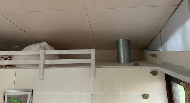
The shower steam must have been leaking into this room every day of the 14 years of this house’s life. Luckily, for most of that time the room was very draughty. But I recently sealed up gaps in the ceiling and walls.

Humidity levels in Bedroom 3
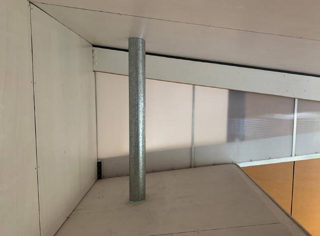
On 4 July 2024, I was up a ladder doing some more gap sealing in that room when I happened to notice condensation on a window. This window is hard to see: it is 2.5+ metres above ground, and covered with flyscreen and blinds. To get access to it I had to climb up the outside. What I found was shocking.
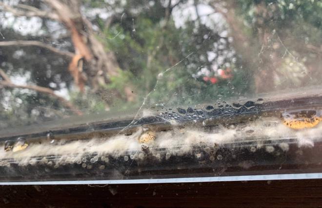
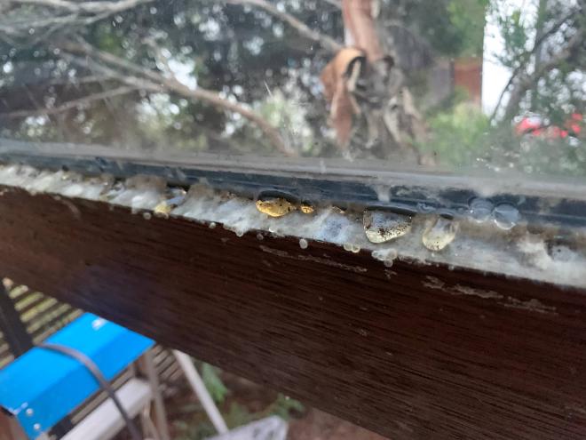
Humid air had leaked behind the secondary glazing (acrylic sheet) and condensed there. I found the same kind of mould in the adjacent window, which had been blocked off with a rigid insulation panel.
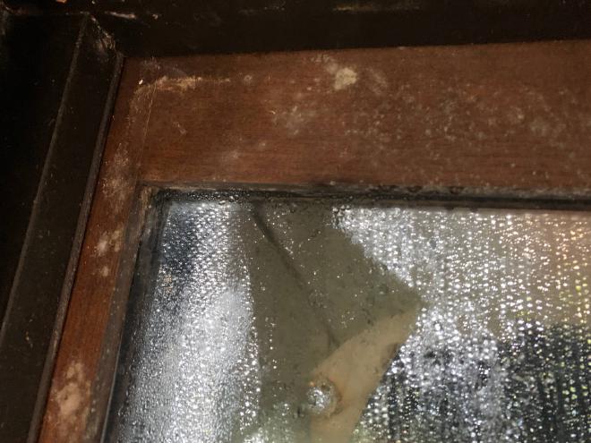
It would be easy to blame this on the secondary glazing and the insulation panel. They certainly contributed to the problem. But I have dozens of other windows with secondary glazing, and 3 other windows blocked off with insulation panels; none have had condensation issues.
Fortunately, there was no apparent structural damage. Once the mould was cleaned away the timber looked and felt normal. I cleaned it with vinegar. Of course, I sealed the exhaust fan cutout. Then I ran the dehumidifier in the room.
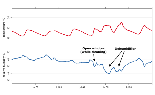
What can be seen though, in the plot, is that humidity levels rose again afterwards (not quite to the same level). So humidity was still too high.
Indoor Air Quality #
You don’t want to be rebreathing a lot of air from your or other people’s lungs. I mean, it’s pretty obviously a bad idea. This kind of pollution is indicated by the level of CO2 in the air. Also, CO2 itself causes fatigue at high levels, and enables pathogens to survive longer in air.
I switched on to indoor air quality when I built an airtight studio pod: CO2 levels rise rapidly in that small space depending on the number of people inside.
I didn’t think to check the CO2 levels in my house however, because it had always been so leaky. But I had done a lot of gap sealing work. When I did eventually start to monitor it I was in for a surprise. For reference:
- fresh outdoor air is around 400 ppm
- effects on sleep quality start above 1000 ppm
- my CO2 monitor sounds an alarm at 1400 ppm

It turned out that CO2 averaged around 1000 ppm in living areas with 2 or 3 people present. When we had a gathering of 8 people, the level reached 1400 ppm after 2 hours.
What was more shocking was what happened in Bedroom 3 overnight (with 2 people).

High CO2 levels in Bedroom 3 overnight
This is not healthy. Clearly something had to be done. As an immediate response, yes, windows were opened. But that is not pleasant in a Canberra winter.
For completeness, I should mention that indoor air quality can also be affected by outdoor sources such as traffic and bushfires. Here is an article about the effectiveness of air filters.
Ventilation system #
The solution to mould and indoor air quality generally is continuous ventilation.
Planning #
There are several strategies for continuous ventilation of homes. The most efficient is Heat Recovery Ventilation (HRV) also known as Mechanical Ventilation with Heat Recovery (MVHR). A heat exchanger transfers heat energy from exhaust air to intake air (in winter). And vice versa in summer. The downside is some cost and complexity, although a significant part of the cost and effort is installing ducting, which would be needed in any system, and the heat exchanger is a passive component (no moving parts).
I had installed HRV in the airtight studio pod I built. But that was a “distributed” HRV: a pair of units fitted into the wall, each with its own fan and heat exchanger. A whole house is better suited to a “centralised” HRV: a ducted system. Why?
- the cost of several distributed units could be higher than one centralised unit
- it would require an electrician to do the wiring (very expensive)
- most distributed units switch flow directions every 60 seconds or so, the sound of which is annoying
- there would have to be more external penetrations.
A centralised HRV unit should be located where
- it can be ducted to outside
- lengths of duct runs to each room are minimised
- the fan noise will not be problematic
- drainage is available (for condensation).
Here are some common HRV mistakes for anyone thinking of doing this.
The site I decided on was a dropped ceiling in the Family room, which is above the Kitchen cooktop and Laundry.
And here is my ducting plan. Blue lines are ducts to supply air vents; red lines are ducts to extract air vents. This is a “radial design”, which splits off all ducts immediately through distribution boxes.

Ducting plan
Basically, air is extracted mostly from bathrooms and kitchen; and fresh air is supplied to bedrooms and living areas. Specifically:
| Supply | Extract |
|---|---|
|
|
I excluded Bedroom 1 because it is relatively leaky, is always cold, and can be zoned off from the rest of the house.
Here are two different ways to decide on the required airflow rate:
- My conditioned floor area is about 140m2 with 3.4m ceilings, which equals a volume of 476 m3. For a nominal airflow rate of 0.4 exchanges per hour, that is 190 m3/hr.
- My desired air extraction rates at each point: Bathroom, Ensuite, Kitchen each 15 L/s; Family, Pantry each 6 L/s. This adds up to 57 L/s, which is 205 m3/hr. A similar result.
In either case, this nominal airflow rate should only be about 60% of the maximum/boost rate (used for occasional purging), which means the maximum rate should be around 320 m3/hr.
System #
The HRV unit I decided on was Dantherm RCV 320 P1 for $4900. It has a maximum airflow rate of 320 m3/hr. As far as I can tell there is not much to choose between this and similar products from Stiebel Eltron and Fantech, apart from being about 15% cheaper (based on some prices I saw at the time of writing). A cheaper option that could work well is Mitsubishi Lossnay ~$2000. I decided against it because it does not have automatic adjustment of fan speed based on humidity.
The ducts, vents, distribution boxes, and plenum boxes were Alnor (systemy wentylacji) products. I bought everything from Dehum and they went above and beyond to help me plan the system. Total cost $8000.
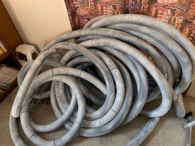
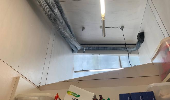
Ducting #
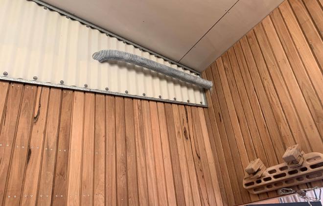
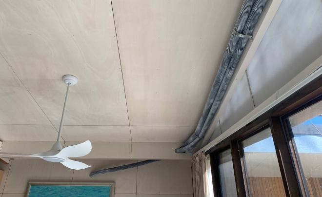
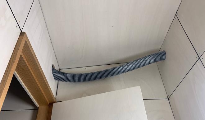
I ran semi-rigid 75mm ducting inside the thermal envelope. This is preferable to running ducting in an unconditioned roofspace or under the floor, because of thermal losses. In any case, I do not have either a roofspace or an underfloor space. It came grey; I gave it a rough spray of white paint.
Then I made a lot of holes in the walls. Remembering that there are electrical cables in there. Don’t try this at home kids.
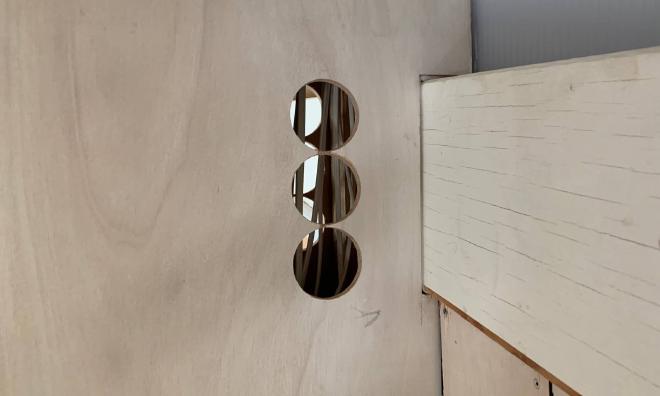
Quite a lot of holes as it turned out. I used a hole-saw drill bit. It was worth buying a proper Cobalt one.
A few challenges:
- The 76mm holes I drilled were too tight. I could get the duct through, but not without scraping off the paint. I had to expand the holes a bit by sanding them. Flecks of paint still went everywhere.
- A couple of times I drilled holes in the wrong spot. Usually because I had not expected a stud to be in the way. The duct is really inflexible over the short distance from one side of the wall to the other, so the holes had to be well lined up.
- One time I cut the duct a bit too short for comfort, and it was a struggle to get it connected at both ends.
- In two places (Living room and WC) I did not want the plenum box to be visible, so I took off a wall panel to install the plenum box inside the wall.
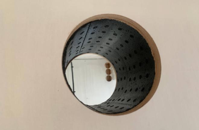
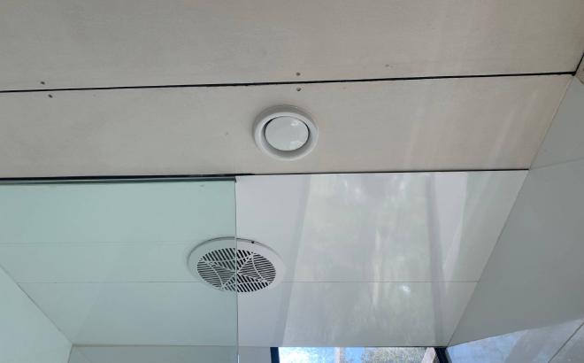
Supply and extract vents #
The 75mm vent plugs into a plenum box which has a 100mm outlet for a vent. The vents for supply and extract are slightly different as they are optimised for diffusing vs sucking. The airflow through each can be adjusted by twisting the head.
I ran into a problem with this vent in Bedroom 2: the wall was unexpectedly thick, 180mm. That was too thick for the neck of the plenum box to reach the other side. I ended up taking off a wall panel and spanning the gap with larger diameter pipe; I could then plug the plenum box into one side, and plug the cut-off neck of another one into the other side to take the vent.
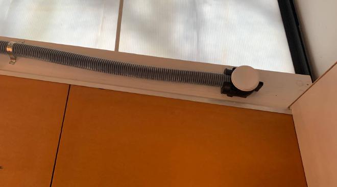
I had the same problem, an extra-thick wall, with this extract vent in the Kitchen.
But this time I did not want to take off a wall panel. So I extended the neck of the plenum box with a duct joiner from Bunnings.
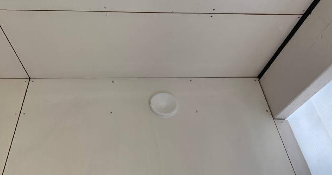
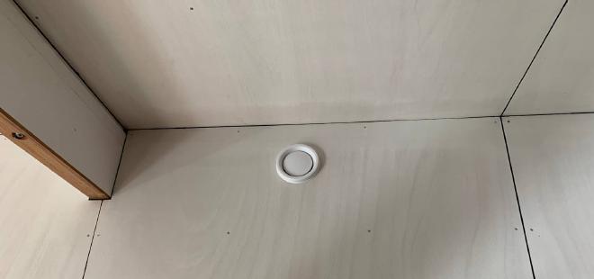
For this extract vent in the Bathroom, I was able to come in through the dropped ceiling.
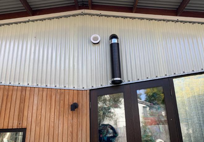
Intake and exhaust #
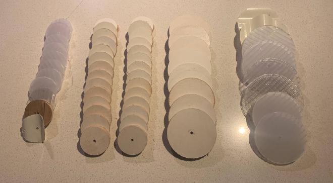
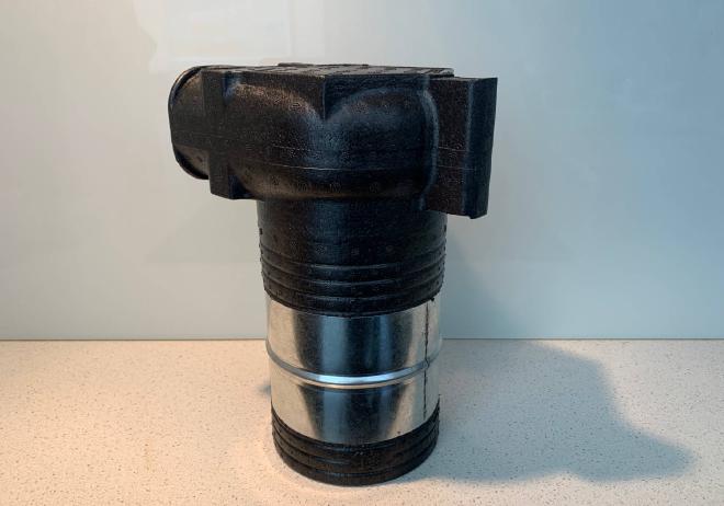
The ducts to and from outside need to be insulated, as they carry cold air through a warm space. These ones are rigid, made from expanded polypropylene.
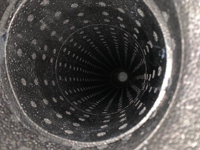
These are 125mm diameter ducts. That’s the inner diameter. The outer diameter is 156mm. So I had to use this monster to make the holes in the external wall:

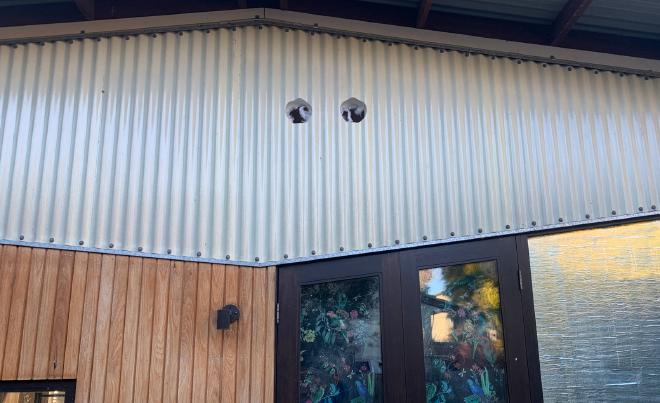
The intake should not be too close to the exhuast vent, for obvious reasons. So I used a bend piece to send the exhaust away some distance. I covered the end of it with flywire. For the supply vent I just plugged in a $15 grille cover from eBay.
Integration #
Here is the HRV unit completely installed. It is mounted on the wall. I plugged the distribution boxes (splitting off into 5 ducts each) directly into the unit, which is unusual. (If the distribution boxes were any bigger they would not have fitted there). The condensation drain, power cord, and control panel drop down into the laundry.
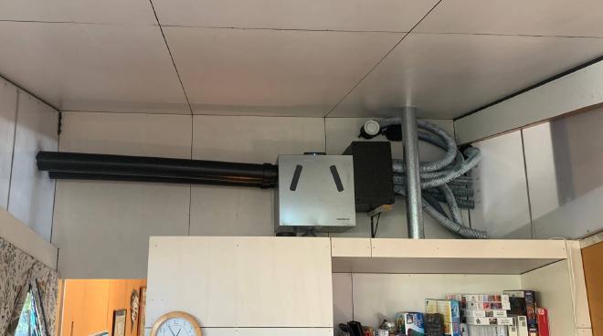
What about aesthetics?
Meh. Function takes precedence over form. Anyway I quite like industrial style.
Calibration #
Once the unit is switched on it must be calibrated, which means adjusting the fan speeds to match the desired flow rate for the home; and also balancing intake with exhaust rates so that air doesn’t leak through elsewhere.
It is possible to do this using the control panel on the unit, but it is easier and more precise to use the Dantherm software on a connected laptop (Windows only unfortunately).

Dantherm PC tool
Here is my calibration setup:
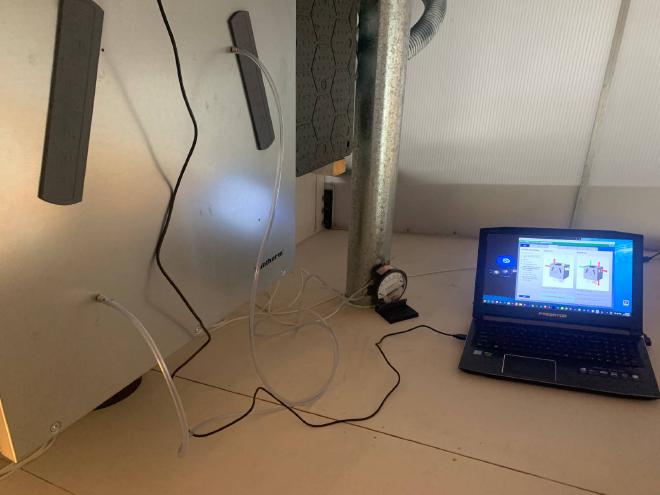
You need a differential pressure gauge (manometer) to measure the pressure drop from one side of a fan to the other. I bought a used analog one $48.50 from eBay. Then you look up a chart (or use the software) to see what pressure drop corresponds to your desired airflow rate.
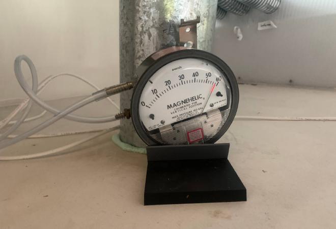
In my case for an airflow of 191 m3/hr I needed a pressure drop of 58 Pascals (in the exhaust fan). To reach that I had to increase the exhaust fan speed to 3096 rpm. For some reason the target pressure drop for the intake fan is always lower (about 10% lower); this may be because incoming cold air expands as it is heated, or because of extra pressure inside due to warmer air? In my case the target pressure drop for the intake fan was 50 Pascals, which I reached with a fan speed of 2004 rpm.
UPDATE 2024-08-03: It turned out that my initial calibration was wrong because the ball pump needles I used to plug the gauge into the unit were too short. They weren’t getting all the way through the insulation layer so weren’t getting a good reading. When I redid it, the situation was reversed: extract fan speed was lower at 3050 rpm, and supply fan speed was higher at 3860 rpm. This makes more sense to me because my supply lines are longer and more circuitous than my extract lines.
UPDATE 2024-08-08: I was a bit unhappy with the high supply fan speed, because of the sound it makes (although the system usually runs at a low level anyway). Why was the supply fan speed calibrated to be so high? Well, to overcome the resistance in the airflow path (static pressure). I had thought it was just the length of the ducting that was to blame, but then I remembered the external vent cover. When I looked closely, the insect mesh built in to it was rigid plastic that blocked more than 50% of the area! So, I replaced this with fine flywire mesh and recalibrated. The nominal supply fan speed came down significantly from 3860 to 3390 rpm.
This calibration process sets the nominal airflow rate which is called “step 3”. Step 2 is defined as 70% of that, and step 1 I set to 35%. Step 4 is always max rpm, used for purging if needed.
Here is an article describing another way to balance an HRV.
Operation #
The unit can be operated by a simple wired control panel, or by an app. All I had to do was plug in an ethernet cable and open the app while connected to the same wifi network. The app is fun because you can see the heat exchanger in action. It’s like magic.

Dantherm Residential app
There are three main operating modes: manual, automatic, and scheduled. Automatic adjusts the airflow rate based on humidity detected in the extract air; this is useful when showering or cooking. It is possible to fit a CO2 sensor or VOC sensor too, apparently. But for now I find that I have to use either manual mode or a schedule when there are more than a few people in the house, to keep the CO2 levels in check.
Results #
It’s been running for a few days now. CO2 levels have been averaging around 700 ppm where they were 1000 ppm previously, indicating improved air quality. I could probably run it harder but I’m happy with this level for now.
UPDATE 2024-08-03: Bedroom 3 overnight test. Running at “step 2” (supplying about 35 L/s), the CO2 level in occupied Bedroom 3 averaged 1200 ppm. That is a lot better than it was before (up to 2800 ppm). And despite supplying 35 L/s of fresh air, the house stayed 18°C above outdoor temperature (15° vs -3°) with no heating overnight.
UPDATE 2024-08-04: Bedroom 3 overnight, same conditions but with door open: CO2 averaged 900 ppm. That is significantly better than with the door closed. Therefore, the airflow path through the 10mm door undercut is not enough. I have ordered these sound-dampening door vents from Tight House.
There has been a noticable change to humidity levels throughout the house:
Study: temperature and humidity before and after turning on HRV Bedroom 3: temperature and humidity before and after turning on HRV (dehumidifier run at end) Family room: temperature and humidity before and after turning on HRV


More subtly, I think temperatures have been evened out a little bit between rooms: colder rooms receive airflow with heat harvested from Living (which has solar gain, hydronic manifold, and cooking).
I expect that we will see benefits in summer too. The HRV has a function to bypass the heat exchanger for use on summer nights: it is then simply circulating cool outdoor air throughout the house.
Conclusions #
It is bizarre that we build houses in cold climates without considering the need for fresh air in winter. We rely on leaks — the mistakes of builders and electricians, and the vagaries of the wind — for our fresh air.
It is commonly believed that homes don’t need continuous ventilation unless they are super airtight. When I or others talk about HRV on MEEH, a popular Facebook group, the frequent response is that it makes no sense unless you know that you have a tight house.
But how many people monitor their CO2 levels? How many people do not know they have a problem?
John Konstantakoloulos of Efficiency Matrix has said
“Having a known good course of air is good for any home no matter how leaky it is. Air tightness just improves the effectiveness and efficiency of HRV”.
I agree.