
Materials #
The design was based on a structural timber frame. I preferred this to a steel frame which can act as a thermal bridge, allowing heat energy through. That said, I think steel frames can be a good option when combined with continuous external insulation. For example, Joost Bakker promotes steel frame construction. Also, I didn’t look as seriously at Structural Insulated Panels or CLT as I probably should have.
Summary of the timber frame:
- floor & walls
- 90x45 H2 (blue) treated pine
- roof
- 140x45 H3 treated pine, mostly
- external cavity battens
- 42x35 H3 treated pine; some wider ones at corners
- internal cavity battens
- 42x35 H2 treated baltic pine; some wider ones at corners
- floor board & roof board
- 17mm structural plywood
- braceboard (wall sheathing)
- 9mm structural plywood
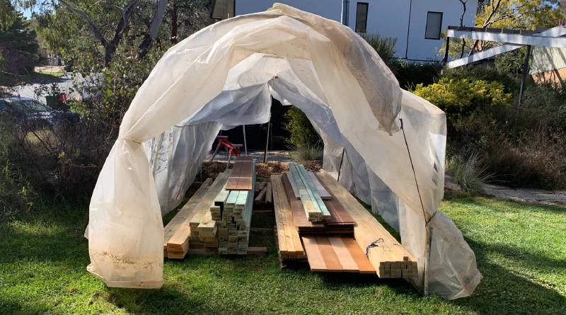
In a previous obsession I had built a greenhouse out of PVC conduit bent into hoops covered with plastic sheeting. This came in handy to keep the timber dry. Probably not really necessary… but if it does get wet, timber should be allowed to fully dry before it is closed in.
Floor #
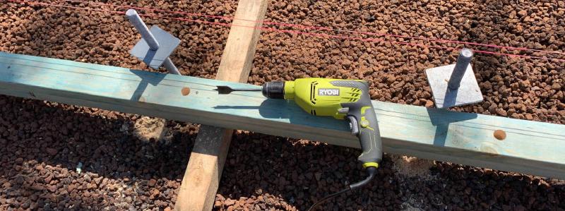
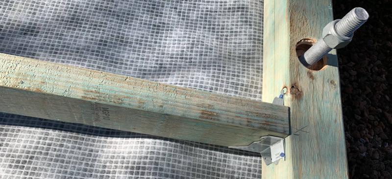
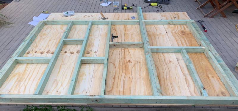
Continuing from where we left off on the previous page. Pairs of 90x45s were glued-and-screwed together to form 90x90 floor beams. (for some reason this is much cheaper than buying actual 90x90 beams). To fit them onto the rods, I marked the positions of the rods then drilled through with a 25mm spade bit. Then a larger diameter hole drilled down half way, so that a nut can be screwed down into it.
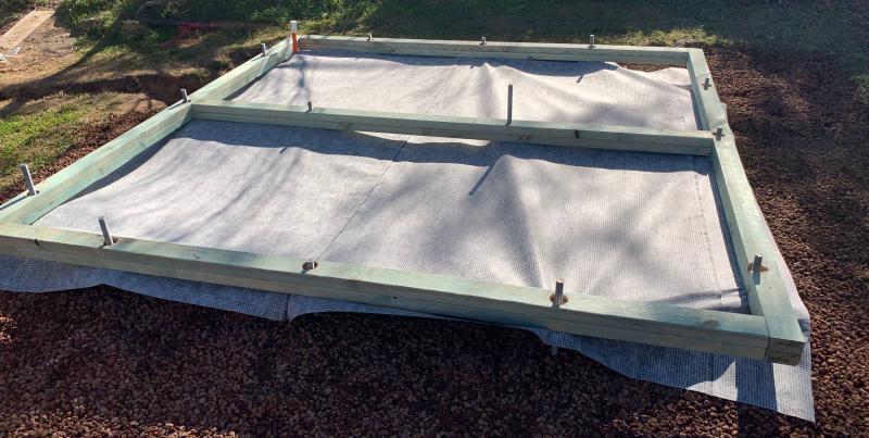
Before securing the beams, I fitted a sheet of vapour-permeable wrap to sit under the floor structure. This prevents wind-washing of the insulation, and hopefully stops things making a home in the insulation too. Then I screwed the beams together at the corners.
My original idea was to put the insulation in first, so that it would protect the wrap from sparks - but the glasswool insulation fibres themselves burned. I should have cut off the rods before laying the wrap. Anyway… I managed to tape up most of the holes.
I made sure that the electrical conduit from the trench - that would have wiring run through it later - came up just inside the floor beam. See Electricals page.
I had to measure the length of each joist before cutting: the frame wasn’t perfectly square because of wobbles in the positions of the rods. They were fastenerd to the beams using joist hangers.
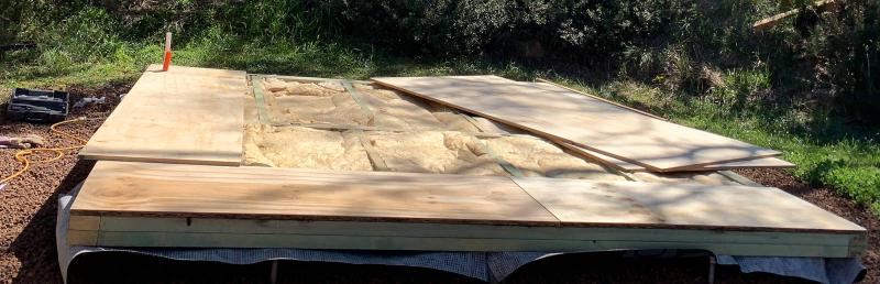
A total of 4 battens were attached to the underside of the floor frame, perpendicular to joists, in order to hold up the wrap and insulation.
To fix the sagging I pushed concrete blocks in under the middle of the battens. It was difficult and annoying, but it worked ok in the end.
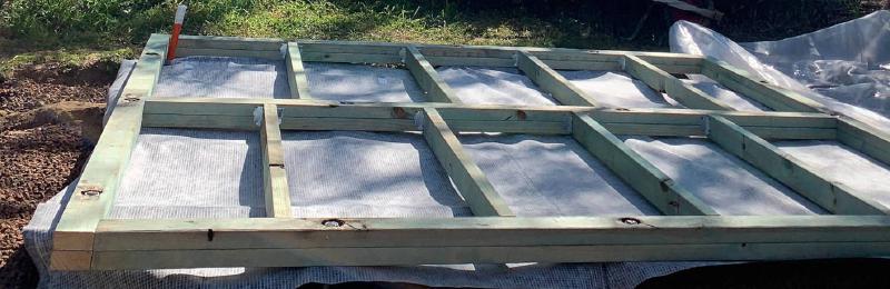
Finally I could place 90mm insulation batts. I had the joists at a standard 600mm spacing so mostly the batts could fit in without trimming.
The whole 3m x 3m frame was to be covered with a plywood subfloor. Since the plywood sheets were 2400x1200 this involved some cutting (with a circular saw).
I joined the edges of the boards - and around the electrical conduit hole - with a polyurethane sealant.
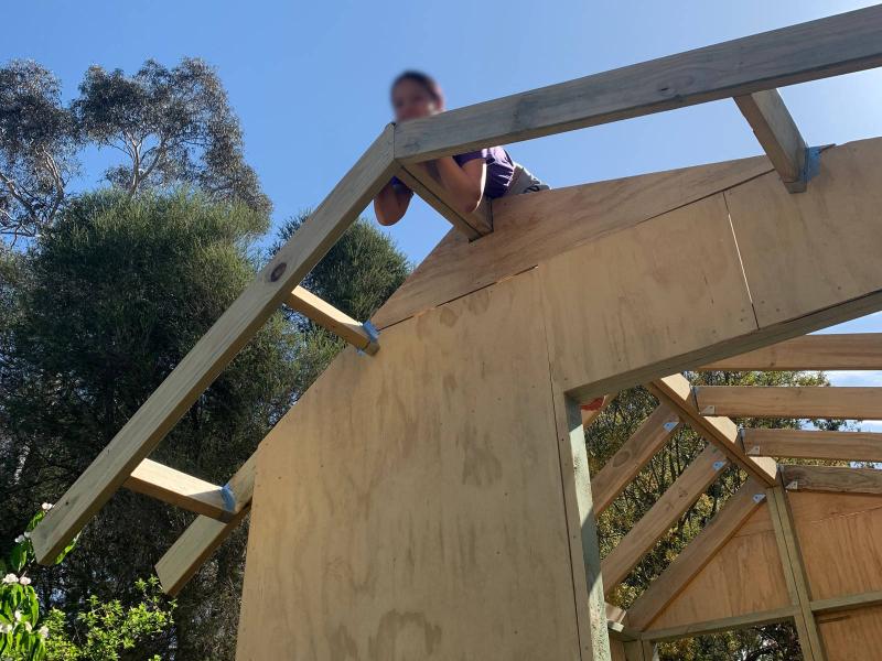
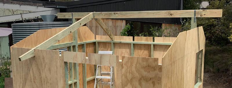
Walls and roof #
The main structural idea with this kind of cathedral design (gable roof with vaulted ceiling), is to support the ridge beam with posts at each end. Then the rafters won’t be pushing out the other walls, rather they will be helping to hold the walls together.

I spaced the wall studs at 600mm where possible, but had to work around the posts and window frames.
After I had a wall together and made it square, I nailed on 9mm plywood sheathing to brace it, i.e. prevent it from leaning left or right. This braceboard also served to hold the structure together and resist wind uplift, because it extended down to be nailed onto the floor beams, and also extended up to be nailed on to the outer 2 rafters.
With each wall assembled, they could be tilted up and secured.
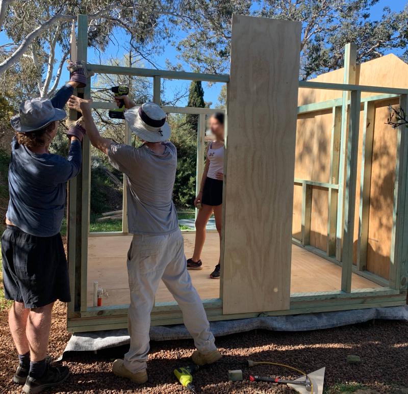
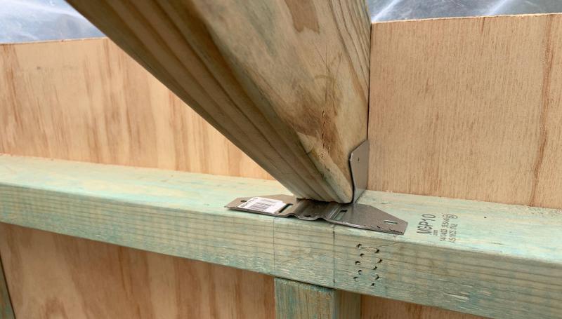
I used nailplates where wall top plates meet at the corners.
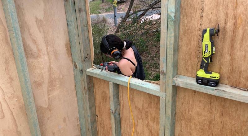
Of course the braceboard had to be cut out for window frames, as well as along the slope of the roof and for rafter tails.
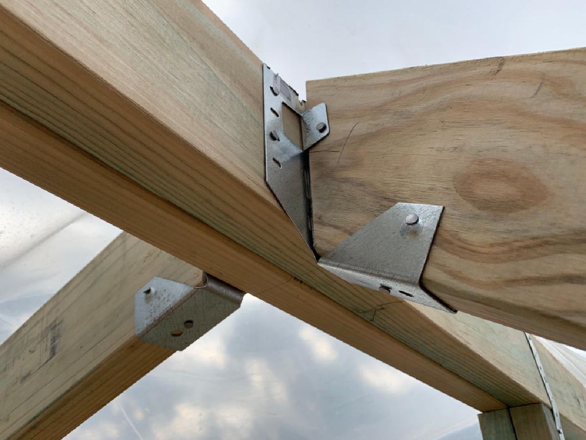
The ridge beam was secured to the posts with structural steel strapping, and nails.
Rafters were notched to fit on to the wall top plate. Also, the rafter tails on the door (north) side were tapered to give a little more headroom.
Rafters were fastened to the ridge beam with rafter hangers, also known as slope/skew hangers (see title image on this page). I was also able to cut these in half to make brackets suitable for securing to the wall top plate.
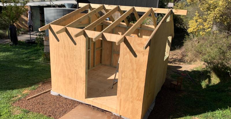
The rafter tails obviously form an eave on the front and back of the roof; all that is needed is to screw a plank (“soffit bearer”) along the ends. 140x45 on the back end, and 70x45 on the front (tapered) end.
Eaves on the gable end walls are less straightforward. These are called rake eave ladders. The ladder is formed by fastening pieces sticking out from the outermost rafter (in line with the ridge beam). Then soffit bearers are screwed on to those.